Classification
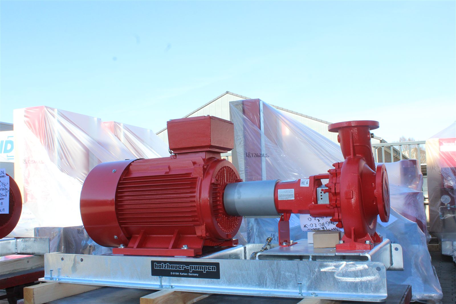
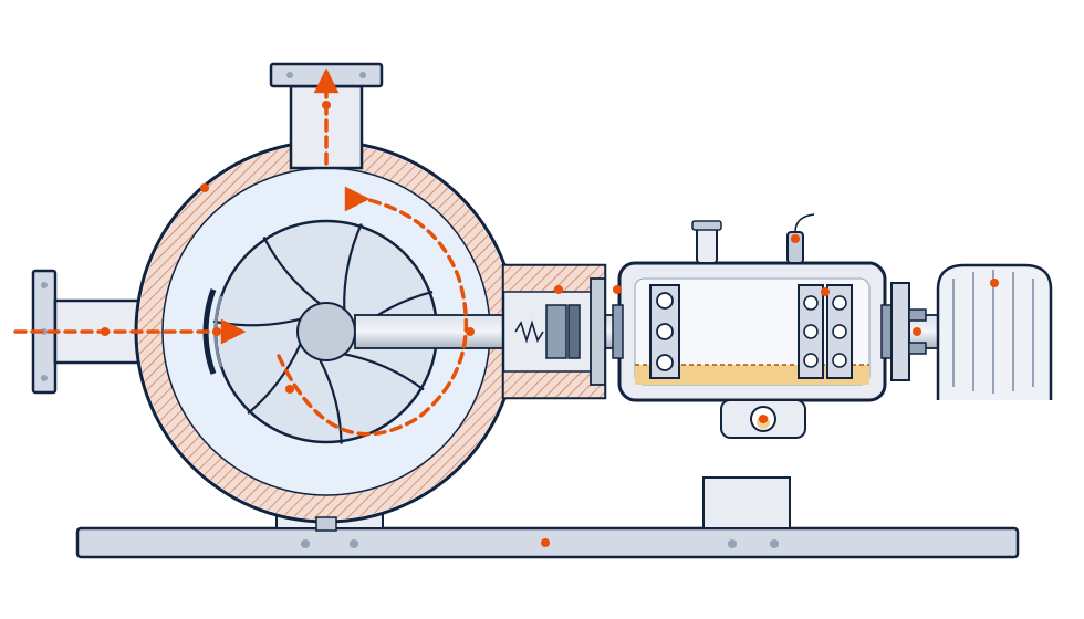
A rotodynamic machine — principle Rotodynamic, family Pumps, class Energy Addition to the Fluid (the full chain is in the breadcrumb above). Class PU at level 6 (equipment unit) of the ISO 14224:2016 taxonomy. The fundamental distinction from positive-displacement pumps: the centrifugal transfers energy to the fluid continuously, through change of angular momentum — not by trapping a sealed volume. The direct practical consequence: the pump does not decide alone how much flow and pressure it delivers — the piping, equipment and valves of the installation it is connected to decide (the Working Principle section shows exactly how).
And, for that same reason, it does not run the same risk as a positive-displacement pump if the discharge is blocked: because some internal clearance always lets liquid recirculate (the clearance between impeller and casing — see wear rings, further down), the pump never gets trapped against a truly dead-end path. Closing the discharge valve does not make pressure rise without limit — it makes flow fall, the pump start recirculating its own liquid internally, and head stop climbing at the maximum value the machine's own curve allows (shutoff, Working Principle section). All the mechanical energy that keeps coming in no longer becomes pressure: it becomes heat, warming the trapped volume of liquid — in high-energy pumps, enough to vaporize the fluid internally and destroy the seal within minutes, with no casing rupture at all.
It is the most numerous rotating equipment in the process industry — typically more than 80% of the rotating fleet of a refinery or chemical plant — and accounts for 30–40% of rotating-equipment maintenance cost (Bloch & Geitner). That double condition (ubiquity + cost) makes the centrifugal pump the first asset of any serious reliability program.
Working principle
Where the energy comes from — Bernoulli first, Euler second
The simplest way to understand a pump is through energy conservation — the same Bernoulli equation used for any flow, just with an extra term for the energy the pump injects:
- — static pressure [Pa], at points 1 (suction) and 2 (discharge).
- — mean fluid velocity [m/s], at 1 and 2.
- — elevation (geometric reference height) [m], at 1 and 2.
- — fluid density [kg/m³].
- — gravitational acceleration [m/s²].
- — the specific energy the pump adds to the fluid, the head [m of fluid column] — this is what we are solving for.
- — sum of friction losses between 1 and 2 [m].
Rearranging to isolate : the pump must deliver exactly the energy missing to take the fluid from state 1 to state 2 — overcoming the pressure difference, the velocity difference, the elevation difference, and the friction losses along the way. That is precisely the calculation, worked out for the real installation, that sizes the pump (the "Pump in the system" section below shows how this becomes the system curve).
Bernoulli explains how much energy is needed — but it treats the pump as a black box. To understand how the impeller physically delivers that energy, the tool is Euler's turbomachinery equation:
- — theoretical head (the energy the impeller delivers before any losses) [m].
- — blade tangential velocity [m/s]: , where is the shaft's angular velocity [rad/s] and is the impeller radius at that point [m] — this is why impeller diameter is one of the two variables (alongside speed) the manufacturer uses to size and select the right pump for a given duty point.
- — tangential component of the fluid's absolute velocity [m/s].
- — gravitational acceleration [m/s²].
- Subscripts and — impeller inlet and outlet, respectively.
With purely radial inlet (, the usual design), the expression collapses to : all the head is born at the impeller periphery. Since grows with radius and with speed, those two variables dominate performance — which is why reducing the impeller's outer diameter (trimming, a controlled mechanical cut) is the standard way to adjust a catalog pump to a specific duty point without changing the casing or the motor.
The real head delivered falls below the theoretical through three families of losses, each with its own physical cause:
- Slip: the fluid is not perfectly guided by the finite number of vanes — part of the angular momentum "escapes" before converting into pressure. Typically subtracts 10–25% of the Euler head; more vanes, more backward-curved, less slip.
- Hydraulic losses: friction on internal surfaces and incidence shock when the pump runs away from the flow the vanes were designed for — grow quickly away from BEP (below).
- Volumetric losses: part of the already-pressurized liquid recirculates back through the wear-ring clearance instead of reaching the discharge — the same clearance that, at the extreme of a blocked valve, keeps pressure from rising without limit (Classification section).
H–Q curve, the best efficiency point (BEP) and minimum flow
Every pump's performance is summarized in a head × flow (H–Q) curve, factory-measured together with the associated power, efficiency and NPSHr curves — the interactive widget right below this section makes the curve's shape and the effect of speed tangible. Three references on that curve carry direct reliability consequences:
- BEP (Best Efficiency Point) — the point on the curve where hydraulic efficiency peaks. It is the central reference of operational health, not a catalog footnote: the farther the pump runs from BEP — flow much higher or much lower — the greater the internal recirculation, the radial shaft load and the vibration. The recommended operating range, the POR (Preferred Operating Region, ANSI/HI 9.6.3), is 70–120% of BEP flow; the AOR (Allowable Operating Region) is the manufacturer's absolute limit — running outside the AOR consumes bearing and seal life at an accelerated, not gradual, rate.
- MCSF (Minimum Continuous Stable Flow) — the real lower bound, distinct from simply "below 70% of BEP": it is the flow below which suction recirculation becomes severe enough to generate unstable vibration and heating that the pump cannot dissipate in continuous service — more restrictive than the POR in high-specific-energy pumps. Below it, sustained operation is not advisable even with good maintenance; the automatic recirculation (ARC) valve or minimum-flow line exists precisely to guarantee this minimum flow when the process demands less.
- Curve stability — a curve continuously rising to shutoff (maximum head at zero flow, typically 110–120% of BEP head in radial machines) has a single possible operating point for each head. Flat or drooping curves admit two different flow points at the same head — a source of hunting and unstable load sharing whenever two pumps run in parallel. API 610 requires a continuously rising curve whenever parallel operation is present.
The pump in the system — who decides the operating point
The installation the pump is connected to — the piping, the process equipment, the valves — imposes the system curve:
- — head the system demands from the pump to deliver flow [m].
- — static head: the elevation and/or pressure difference between the two reservoirs the pump connects, the portion that does not depend on flow [m].
- — system resistance coefficient (piping, valve and fitting friction) [s²/m⁵], derived from the piping itself (diameter, length, fittings).
- — flow [m³/s].
The real operating point — the flow and head the pump actually delivers — is always the intersection of that system curve with the pump's own H-Q curve: neither one "wins" alone, the point is where the two agree. Every operating action, at bottom, is editing one of these two curves — and the most valuable diagnostic habit for this equipment is asking exactly which curve changed:
- Closing (throttling) the discharge valve raises — the system curve gets steeper, and the intersection point slides along the PUMP's own curve toward lower flow and higher head.
- Changing a tank level or a vessel's pressure changes — it shifts the entire system curve up or down, without changing its shape.
- Varying speed via a VFD (variable frequency drive, the electronic equipment that converts the grid's fixed frequency into a variable one, continuously controlling motor speed) shifts the pump's curve, not the system's — it is the only one of the three actions that changes the machine itself, and it does so following the affinity laws (next).
Reading cavitation, recirculation or motor overload as "the operating point moved" — and asking which curve was edited and why — resolves most field diagnoses before the pump is ever opened.
- Parallel operation (two pumps on the same discharge) adds flows at constant head — but the real gain depends on the system curve's steepness: with a steep (friction-dominated) system, the second pump adds far less than double the flow, and both drift away from BEP. Flat or drooping curves in parallel share load unstably (one pump ends up "carrying" the other).
- Series operation (one pump feeding the other's suction) adds heads at the same flow — the classic booster arrangement; mind the pressure class of the downstream pump's casing, which receives the sum of both pressures.
Specific speed — the impeller's shape in one number
Different impeller designs deliver the same BEP (same nominal flow and head) with radically different geometries — a narrow, large-diameter wheel, or a wide, compact propeller. The specific speed is the practically-dimensionless number that identifies which of these shapes best solves a given flow-head pair, independent of the machine's physical size:
- — specific speed, computed at the BEP.
- — speed [rpm].
- — flow at BEP [m³/s].
- — head at BEP [m].
| Geometry | Typical profile | Behavior | |
|---|---|---|---|
| 10–40 | Radial (high head, low flow) | Process, high pressure | Flat curve; power grows with flow |
| 40–160 | Semi-axial / Francis | Water, condensate, large flows | Intermediate |
| > 160 | Axial (high flow, low head) | Intake, circulation | Steep curve; maximum power at shutoff |
Peak attainable efficiency is also a function of (practical maximum around 40–60; very low pays disproportionate disc friction relative to useful head) — and cavitation sensitivity grows with impeller-eye energy, which also scales with . It is the first axis of the clustering in the Types section, below.
Affinity laws
A direct consequence of (and ): varying only the speed of the SAME impeller — the VFD case — shifts the whole H-Q curve predictably, with no new test required:
- — flow [m³/s or m³/h], at the homologous point (same relative position on the curve).
- — head [m].
- — absorbed power [W or kW].
- — speed [rpm]; subscripts and — reference condition (e.g. nominal speed) and new condition (e.g. speed reduced by the VFD).
Numerical example: reducing speed by 20% (from to ) delivers (−20% flow), (−36% head) and (−49% power) — the cubic dependence of power on speed is the central economic argument for variable-frequency drives: a modest flow cut already gives back almost half the energy consumed.
Two reliability readings follow directly from the same law: NPSHr also falls with — reducing speed is, in practice, an active tool against cavitation, not just an energy-saving one; and, in the opposite direction, small speed increases above nominal overload the driver and bearings disproportionately (power rises with the cube) — never run above the design speed without re-evaluating the whole mechanical chain.
Power, start-up and thrusts
- Power behavior: in radial machines (low ) power grows with flow — start with the discharge closed (lowest starting load) and the minimum-flow line open; the motor is sized for end of curve (run-out), not for BEP. Axial machines are the opposite: maximum power at shutoff — start with the discharge open.
- Radial thrust: a single volute only balances peripheral pressures at BEP; away from it the radial resultant grows (maximum at shutoff — Stepanoff), flexing the shaft once per revolution (rotating fatigue, seal wear). A double volute splits the flow into two channels 180° apart and nearly cancels the resultant — standard on large machines.
- Axial thrust: the pressure imbalance between impeller shrouds pushes the rotor toward suction. Balancing: rear wear rings + balance holes (or back vanes); in multistage, opposed impellers (back-to-back) or a balance drum/disc with an equalization line. The residue belongs to the thrust bearing — repeated thrust-bearing failures call for a balance audit, not a "better" bearing.
Efficiency decomposed — where the energy goes
- η_h (hydraulic): friction and incidence shock — falls quickly away from BEP.
- η_v (volumetric): recirculation through the wear rings — doubling the design clearance knocks off whole efficiency points; it is the slow drift that performance monitoring sees (same flow demanding more power).
- η_m (mechanical): bearings, seal and disc friction.
Practical BEP efficiency ranges: ~50–70% in small pumps, 75–88% in well-selected process machines, >90% in large water pumps. Every percentage point is a permanent energy bill — and falling efficiency is a measurable symptom of internal wear before any functional failure.
NPSH — the existence condition of suction
Every centrifugal pump has, at the impeller inlet, a region of minimum pressure — a direct consequence of Euler's equation itself: to convert velocity into pressure, the fluid must first accelerate, and wherever it accelerates most, local pressure drops the most. If that minimum pressure falls below the liquid's vapor pressure, it vaporizes right there — the onset of cavitation, this equipment's signature failure mode. NPSH (Net Positive Suction Head) is the ruler that measures the margin before that happens:
- — available NPSH: how much the installation actually delivers at the pump inlet, above vapor pressure [m].
- — absolute pressure at the liquid surface in the suction reservoir [Pa] (atmospheric, if the tank is open).
- — the liquid's vapor pressure at the operating temperature [Pa] — rises sharply with temperature (see the Cavitation note, Engineer level, for the full curve).
- — liquid density [kg/m³].
- — gravitational acceleration [m/s²].
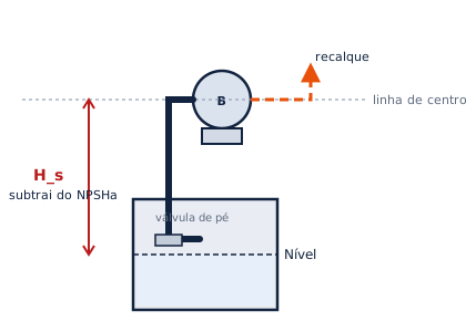
- — static suction head [m]: positive when the pump is above the liquid level (penalizes NPSHa), negative when it is below (favors NPSHa) — the "Pump installation" section below shows the real-world scenarios.
- — sum of friction losses in the suction line (friction + fittings) [m].
This NPSHa, a property of the installation, must exceed NPSHr (required NPSH, a property of the pump — the manufacturer measures it on a test stand and states it on the curve, using the 3% head-drop criterion) with a safety margin: NPSHa/NPSHr ratios of 1.1 to 2.5 depending on the design's suction energy (ANSI/HI 9.6.1:2024); API 610 goes further and requires, directly, NPSHa ≥ NPSHr + 1.0 m throughout the allowable operating region (AOR). Insufficient margin — from excessive suction lift, friction losses larger than assumed, or simply the process heating up (which raises exponentially) — is the most common root cause of field cavitation.
A quick example to make this concrete: an installation with a comfortable NPSH margin at 25 °C can start cavitating severely with no physical change at all — just by the process heating to 70–80 °C, because rises far faster than any other variable in the equation. The Cavitation note (Engineer level) carries the full derivation from Bernoulli, the table and a worked numerical example of the same installation at two temperatures.
Pump installation — flooded, elevated, submerged and variable-level suction
A common misconception: saying the pump "sucks" or "pulls" the fluid in. It does not pull — it pushes, always by a pressure difference. The impeller creates a low-pressure zone at the inlet and a high-pressure zone at the outlet; it is atmospheric (or vessel) pressure pushing liquid from the suction reservoir toward that low-pressure zone that actually moves the fluid to the pump — from there, the impeller pushes the liquid onward to the discharge. Understanding this reframes every installation scenario: what matters is not the distance to the pump, it is the pressure difference available to push the liquid there — exactly what the NPSH equation above quantifies through the term.
Flooded suction (pump below the liquid level): is negative and adds to NPSHa — the most favorable condition, because the liquid column above the pump already pushes fluid into it before the impeller does anything at all. This is the recommended layout whenever plant geometry allows it.
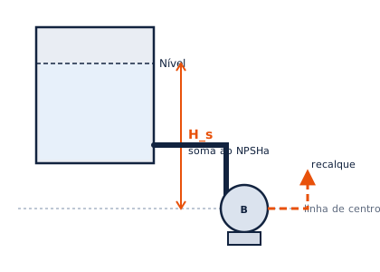
Suction lift (pump above the liquid level): is positive and subtracts from NPSHa — every metre the pump sits above the level is a metre less of margin. Requires priming (the suction line does not fill by itself) and, typically, a foot valve to retain the liquid column when the pump stops.
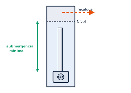
Submerged pump (the rotor+motor assembly immersed in the liquid itself — wells, drainage, intake): removes as a problem altogether (the pump is already at the most favorable level possible), but trades it for another challenge — minimum submergence (ANSI/HI 9.8): the minimum liquid depth above the inlet needed to prevent a surface vortex from dragging air into the nozzle, which degrades effective NPSHa just as much as insufficient elevation margin would.
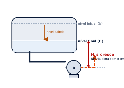
Variable suction level (e.g. draining a tank, a sump, or a tanker truck during operation): the suction line stays fixed, but the liquid level falls over time — worsens progressively during the operation itself, even if the installation was designed with a comfortable margin at the start. This is a classic cavitation scenario that only shows up at the end of the pumping cycle, and one the NPSH audit must evaluate at the worst instant (lowest level), not the average.
The fluid changes the pump — viscosity, density, gas and priming
- Viscosity: catalog curves are for water. Viscous fluid knocks down flow, head and above all efficiency, and raises power — correct with the ANSI/HI 9.6.7 factors; above a few hundred cSt, the comparison with positive displacement almost always wins.
- Density: head in metres does not depend on ρ — but pressure () and power scale with ρ. The commissioning trap: water-testing (ρ = 1,000) a pump selected for light hydrocarbon (ρ ≈ 750) demands ~33% more power — an undersized motor trips during the test.
- Free gas: 2–4% by volume already degrades a standard impeller's head and efficiency; around ~10% the flow separates and the pump loses prime (open-impeller/inducer variants tolerate more).
- Priming: a centrifugal does not pump air — casing and suction line must be full and vented before start-up (foot valve, vacuum priming, or a self-priming variant). Reverse rotation (swapped three-phase leads) delivers low head/flow and vibration — a commissioning check that precedes any hydraulic diagnosis.
- Acceptance and baseline: the ISO 9906 performance test (acceptance grades 1/2/3) at delivery is the baseline against which performance monitoring (PIMS) will measure all future drift — without a baseline, performance-based CBM is guesswork.