Working principle where a rotating impeller continuously transfers energy to the liquid: the angular momentum imposed by the vanes converts into pressure rise. In summary — the full version, with Bernoulli explained first and the complete derivation, is in the Centrifugal Pump handbook — the Euler turbomachinery equation governs that conversion:
- — theoretical head, in meters of fluid column [m]: the energy potential the impeller delivers to the fluid, before subtracting real losses.
- — blade tangential velocity [m/s], ( = shaft angular velocity [rad/s]; = impeller radius at that point [m]).
- — tangential component of the fluid's absolute velocity [m/s].
- — gravitational acceleration [m/s²].
- Subscripts and — impeller inlet and outlet, respectively.
Since the fluid enters with little to no swirl in most designs (), the expression reduces to : all the head is born at the impeller periphery — the larger the diameter and the speed, the larger the theoretical head. In practice, the real head delivered is lower than the theoretical one: part is lost to slip (the fluid is not perfectly guided by the finite number of vanes), another part to hydraulic friction, and another to internal recirculation — the handbook details all three.
H-Q curve and the best efficiency point (BEP)
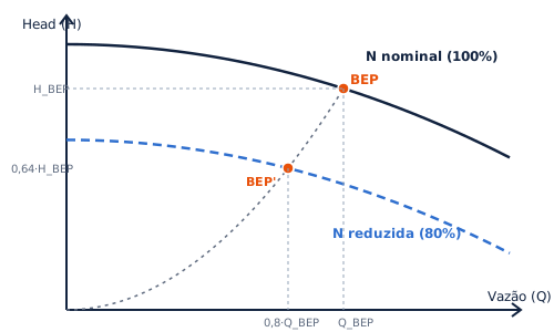
A rotodynamic pump's performance boils down to one curve: the head (H) it delivers falls as flow (Q) rises — more flow demands more fluid velocity inside the impeller, and that velocity "steals" energy that would otherwise convert into pressure. The actual operating point is not chosen by the pump: it is the intersection of that curve with the curve of the system it is connected to (the Centrifugal Pump note details that interaction).
Along that curve there is a point where hydraulic efficiency peaks — the BEP (Best Efficiency Point). It is the central reference of operational health: the farther the pump runs from BEP (flow much higher or much lower than it), the greater the internal recirculation, vibration, wear and susceptibility to cavitation — a large share of this principle's failure modes is born exactly there. The diagram below illustrates the curve's typical shape and the BEP marked on it:
Affinity laws
For the same impeller varying only speed (e.g. via a variable-frequency drive), three proportionalities link the old operating point to the new one:
- — flow [m³/s or m³/h].
- — head [m].
- — absorbed power [W or kW].
- — speed [rpm]; subscripts and — reference condition and new condition.
In practice: cutting speed by 20% cuts flow by 20%, head by ~36% and power by ~49% — the central economic argument for variable-frequency drives. And since the whole BEP slides along that same rule (the diagram above shows the BEP migrating to lower and at reduced speed), required NPSH also falls with — reducing speed is, in practice, a tool against cavitation, not only an energy-saving one.
NPSH — the margin that avoids cavitation
Every rotodynamic pump has, at the impeller inlet, a region of minimum pressure — and if that pressure drops below the liquid's vapor pressure, it vaporizes locally and cavitates. Two numbers summarize that condition: NPSHd (available — how much the installation delivers, a system property: elevation, friction losses, fluid temperature) and NPSHr (required — how much the pump needs to run without cavitating, a machine property, given by the manufacturer). The design rule is simple to state and tricky to apply correctly: NPSHd must exceed NPSHr with margin — the Cavitation note (Engineer level) carries the rigorous formulation, the derivation from Bernoulli, the exact normative margins and a complete numerical example.
Usual types
The criteria below are orthogonal — a given pump combines one of each:
- Flow geometry: radial centrifugal (the dominant one), mixed-flow and axial — specific speed grows in that order; the helico-axial extends the principle to multiphase mixtures (gas + liquid);
- Staging: single-stage × multistage (high pressures);
- Construction/installation: horizontal, vertical, in-line, submersible, axially split case, vertical turbine and deep-well, self-priming;
- Service: cryogenic, circulating, booster.
(handbooks per type in Phase 1) — Main type in the collection: Centrifugal Pump.